This plan is planned based on the following standards:
1. Manufacturing standards
1) GB/T16826-2008 "Electro-hydraulic Servo Universal Testing Machine"
2) GB/T2611—2007 "General Technical Requirements for Testing Machines"
3) JJG139—1999 "Tensile force, pressure and universal testing machine"
4) GB/T3722-92 "Hydraulic Pressure Testing Machine"
5) JJG157-2008 "Verification Requirements for Tension, Compression and Universal Material Testing Machines"
2. Test standard
1) JT/T4—2004 "Highway Bridge Plate Rubber Bearing"
2) JT391-2009 "Highway Bridge Basin Bearing"
3) GB/T17955-2009 "Bridge Ball Bearing"
4) TB/T1893-2006 "Railway Bridge Plate Rubber Bearing"
5) TB/T 2331-2013 "Railway Bridge Basin Bearing"
6) TB/T 3320-2013 "Railway Bridge Ball Bearing"
7) GB 20688.1-2007 "Rubber bearings Part 1: Test methods for seismic isolation bearings"
8) JT/T822-2011 "Lead core vibration isolation rubber bearings for highway bridges"
9) JT/T842-2012 "High-damping vibration isolation rubber bearings for highway bridges"
1. Product use range
1. This machine is used to test the mechanical properties of the finished product of highway bridge rubber bearings.Can be done separately:
1) Plate support
1) Compressive elastic modulus test
2) Ultimate compressive strength test
3) Shear modulus test
4) Shear bonding performance test
5) Shear aging test
6) Friction coefficient test
7) Allowable rotation angle test
2) Basin type support
1) Vertical bearing capacity test of finished support
2) Test of friction coefficient of finished bearing
3) Rotation test of finished product support
3) Spherical steel support
1) Vertical bearing capacity test
2) Bearing friction factor test
3) Measurement of the rotational torque of the support
4) Horizontal bearing capacity test
2. This product can also be used for vertical rigidity test of lead core, high damping, and seismic isolation of building supports.
2. Product introduction
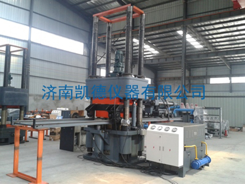
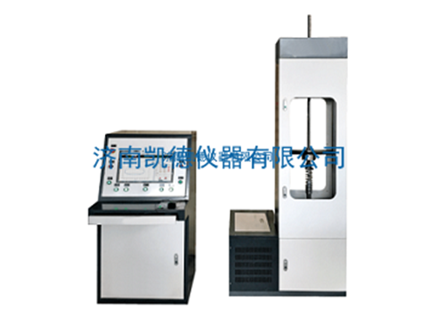
The YAW- J 5000 computer-controlled electro-hydraulic servo compression shear test machine adopts a cylinder-mounted, four-column structure, and the frame has high rigidity and strength and small deformation. It meets the testing requirements of highway and railway bridge slab, basin, and spherical bearings. The space is steplessly adjustable, which is convenient for different height test requirements. Adopting self-developed and proprietary multi-channel closed-loop coordinated loading electro-hydraulic servo control system, computer-controlled coordinated multi-level hydraulic loading, continuous loading and stable, multi-level test force maintenance, automatic load retention, automatic collection and storage of data, drawing curves, automatic Print the test report, the computer controls the test process in time, displays the test force and test curve, and the operation is simple and reliable.
3. Main technical parameters
1. Vertical loading part
1) Maximum test force: 5000kN;
2) Test force measurement range: 0.4%-100%FS (20~5000kN);
3) Test force measurement accuracy: ±1% of the indicated value of test force;
4) The maximum displacement speed of the oil cylinder without load: 0-50mm/min;
5) Maximum stroke of the oil cylinder: 200mm;
6) Displacement measurement accuracy: ±1.0%Fs;
7) Deformation measurement division value (mm): 0.001 (vertical deformation), 0.001 (radial deformation);
8) Deformation measurement: Four grating digital displacement sensors measure the vertical deformation of the sample;
Four grating digital displacement sensors measure the radial deformation of the sample;
9) Deformation measurement range: 0~30mm (vertical deformation), 0~10mm (radial deformation);
10) Test adjustment space: 0~1000mm;
11) Maximum test space: 1000mm;
12) Upper plate size: 820mm×820mm×150mm;
13) Trolley pressure plate size: 820mm×820mm×150mm;
14) The lifting speed of the beam: 200mm/min;
15) Constant velocity test force control range: 0.5kN/s~25kN/s (control accuracy 1%);
16) Constant velocity displacement control range: 0.5 mm /min~50 mm /min;
17) Data processing: computer servo control system and data (test force, displacement) graphic acquisition and processing, etc.;
18) Force measuring method: high-precision ion beam sputtering thin film pressure sensor is used to measure force;
19) Using low damping combined sealing element, the test force remains stable and reliable
20) Control mode: hydraulic loading, electro-hydraulic servo closed-loop control, screen display.
2. Transverse shear
1) Maximum test force: 1000kN;
2) Test force measurement range: 1%-100%FS (10 kN~1000 kN);
3) Test force accuracy: ≤±1%;
4) Adopt single rod double acting piston cylinder, piston stroke 200mm;
5) Propelling speed of working piston: 0~60mm/min;
6) Deformation measurement range: 0~150mm;
7) Displacement measurement range: 0~200mm;
8) Deformation measurement accuracy: ±0.5%FS;
9) Displacement measurement accuracy: ±1.0% Fs;
10) Deformation measurement scale value: 0.01mm;
11) Displacement and deformation measurement: two grating digital displacement sensors measure the shear deformation of the sample;
12) Force measuring method: high-precision load cell measuring force;
13) Advance and retreat of horizontal shearing device: motor drive;
14) Lifting and lowering of horizontal shearing device: adjustment of floating hydraulic cylinder;
15) Load holding function: high-precision imported servo valve load holding, multi-level control of transverse shear force;
16) Using imported combined sealing elements, the test force remains stable and reliable.
17) Control mode: hydraulic loading, electro-hydraulic servo closed-loop control, high-precision load sensor measurement, screen display.
3. Corner part
1) Maximum angle of ejection force: 300kN;
2) Test force measurement range: 2%~100%FS (6kN~300kN);
3) Test force accuracy: ≤±1%;
4) Force measuring method: high-precision load cell measuring force;
5) Deformation measurement: Four grating digital displacement sensors measure the overturning deformation of the sample;
6) Deformation measurement range: 0~30mm;
7) Deformation measurement scale value: 0.001mm;
8) Deformation measurement accuracy: ±0.5%FS;
9) Maximum stroke of working piston: 150mm;
10) Moving speed of working piston: 0~60mm;
11) Displacement measurement range: 0~150mm;
12) Displacement measurement accuracy: better than ±1.0% Fs;
13) Load holding function: high-precision imported servo valve load holding, multi-level control of the cornering force;
14) Imported combined sealing elements are used, and the test force remains stable and reliable.
15) Control mode: hydraulic loading, electro-hydraulic servo closed-loop control, high-precision load sensor measurement, screen display.
Four, performance characteristics
1. Vertical system
1) It adopts a lower plunger cylinder and a four-screw frame main engine, and the test space is steplessly adjustable, which is convenient for test requirements of different heights. The whole machine has high rigidity, small deformation, and accurate measurement data.
2) The base and beam adopt the integral casting structure, and the material is selected ZG310-570. Its structure has reasonable distribution of ribs, large rigidity of the workpiece, and beautiful appearance, ensuring the safety and reliability of the entire part;
3) The beam is movable, which can realize stepless adjustment of the test space, and the adjustment space is 0~1000mm. In addition to satisfying the test of the rubber bearing, it can also do some compression tests of larger samples, which has a greater advantage than the model with the fixed beam on the cylinder.
4) The screw uses 45# high-quality structural steel, and the nut is high-grade ductile iron, which not only meets the strength but also improves the reliability of the screw nut. The screw nut is processed by high-precision machine tools. Heat treatment such as quenching and tempering and shaping to ensure the accuracy of the workpiece;
5) The cylinder has a plunger structure. It is pushed by hydraulic pressure when rising, and falls by its own weight. It adopts casting and undergoes high temperature tempering to eliminate internal stress after casting. It is processed by high-precision machine tools to ensure accuracy. The final process of the cylinder bore It is precisely machined for the honing machine, which reduces the friction of the cylinder piston and improves the measurement accuracy and service life of the testing machine;
6) The oil cylinder adopts advanced composite sealing technology, and the seals are imported from the German Oil Control Group, and have a gap oil film and a two-stage seal. After the two-stage seal, a gap oil return pipe is set to return to the fuel tank. This sealing method ensures the reliability of the cylinder seal, improves the accuracy and stability of the force measurement, and increases the service life of the cylinder and piston; in addition, the plunger type cylinder can replace the seal without removing the cylinder, which is convenient Future maintenance.
7) The piston has a diameter of 500mm and is cast from ductile iron. The piston is a whole entity with a large diameter, which ensures the stability and good rigidity of its high-pressure rod.
8) The cross beam is raised and lowered by means of a screw pair composed of a screw nut.
9) The beam lifting transmission system adopts the following mechanism: the cycloid pinwheel reducer drives the biaxial output forward and reverse to drive the sprocket and chain, and the chain drives the lead screw pair to realize the stepless adjustment of the test space. The four screws have two left-handed and two right-handed, which are characterized by eliminating the influence of the lifting of the cross beam on the starting torque of the screw;
10) The height of the whole machine is 3500mm, the base cylinder is 600mm in the foundation pit, and it is only 2900mm above the ground, which reduces the requirements for the height of the laboratory. The feeding trolley and the shearing device trolley share a guide rail, which is convenient and quick to load and unload samples;
11) A worktable is installed between the feeding and discharging cart (ie, the lower pressing plate) and the piston of the main cylinder, which increases the force strength of the lower pressing plate. A guide post is installed on the worktable to avoid the rotation of the piston during the test and make the test force value more accurate;
12) The vertical force value is measured by a 0.1-level ion beam sputtering thin film pressure sensor. The sensor uses advanced ion beam sputtering and ion beam etching processes, and the strain bridge is directly fabricated on the metal sputtering diaphragm, which significantly improves the long-term instability and creep characteristics caused by the ordinary load sensor pasting process . The pressure of the measured medium directly acts on the metal diaphragm of the sensor to produce a deformation proportional to the pressure of the medium. The strain bridge converts this deformation into an electrical signal corresponding to this pressure, thereby measuring the force value. . The sensor is small in size, high in accuracy, and can withstand high temperature and high pressure, and has high overload resistance.
2. Transverse shear system
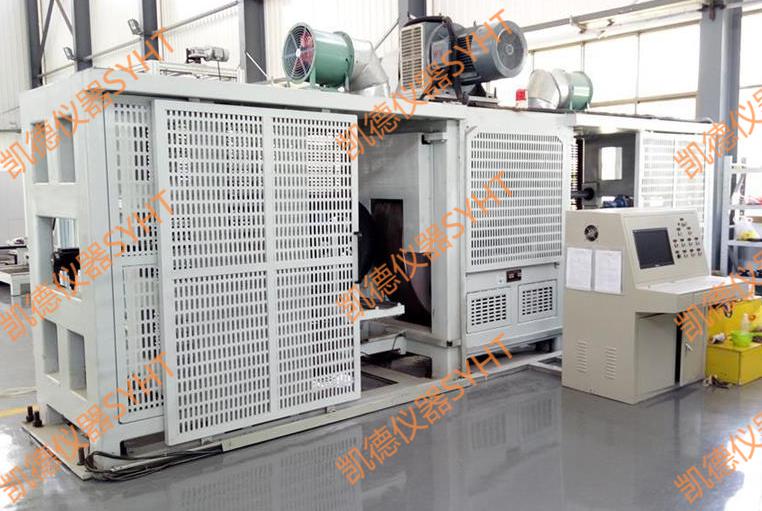
1) The shearing system is composed of shearing cylinders, front and rear beams, pull bars on both sides, shearing middle extraction plates, upper and lower friction plates, top blocks, connecting pins, and shearing carts. The double-acting servo cylinder is used to apply the test force, supported by the shearing trolley, and the floating cylinder adjusts the horizontal position of the transverse shear. The electric walking device of the trolley is equipped with an electromagnetic clutch to adjust the front and rear positions of the shearing device.The shearing trolley lifts and adjusts the horizontal position of the loading device to ensure the accuracy of the shear force value and improve the detection accuracy.
2) Double-acting servo cylinders, connecting rods, friction plates, shear trolleys, floating cylinders and guide rails constitute the main transverse system;
3) The shearing trolley is composed of rollers, servo floating cylinders, guide columns, walking motors and clutch devices;
4) The forward and backward movement of the cutting trolley is realized electrically, without manual pushing, and is equipped with an electromagnetic clutch. The clutch is energized and closed when walking. After the shear test starts, the clutch is de-energized and released. During the test, the trolley will move with the shear deformation of the rubber support. At this time, the resistance of the trolley's movement needs to be minimized, that is, it is not restricted by the walking motor when moving, so that the results of the shear test are more accurate;
5) The horizontal position of the shearing loading device is adjusted by the servo floating cylinder carried by the shearing trolley. The servo floating cylinder automatically adjusts the horizontal position of the shearing cylinder to ensure that the axis of the load cell coincides with the symmetrical axis of the intermediate shearing plate. The accuracy of the horizontal axial force of the sample;
6) The shearing cylinder is a single rod double-acting servo cylinder, which uses imported Gly ring, Steer seal and dust ring to seal, with good sealing performance, long service life and high safety factor;
7) The shear force value is directly measured by a high-precision load cell, with an accuracy of 0.3 and a range of 1000kN, which can withstand large overload loads and has a long service life;
8) The link between the load cell and the piston rod ensures the accuracy of the transverse shear force;
9) Two grating displacement sensors are used to measure the shear deformation of the rubber support. The sensor top rod is in contact with the middle pumping plate and is distributed at both ends of the pumping plate to accurately measure the shear deformation of the rubber support;
10) Equipped with two stainless steel plates with good flatness and smoothness, which fully meets the requirements of the friction coefficient test.
2. Corner system
1) The corner system uses a double-acting servo cylinder to apply force and is fixed on the base of the vertical host.
2) Double-acting servo cylinder, corner plate, spherical rod and supporting seat constitute the main corner system;
3) The corner cylinder is a single-rod double-acting servo cylinder, which uses imported Gly ring, Steer seal and dust ring to seal, with good sealing performance, long service life and high safety factor;
4) The angle of force value is directly measured by a high-precision load cell, with an accuracy of 0.3 and a range of 300kN, which can withstand large overload loads and has a long service life;
5) Four grating displacement sensors are used to measure the corner deformation of the rubber support;
6) The load cell and the piston rod form a ball joint connection through a ball joint (the ball joint connection can be freely centered to ensure the accuracy of the corner vertical force);
7) According to different sizes of samples, the length of the spherical rod attachment can be changed to meet the test requirements of different thicknesses of the test piece.

